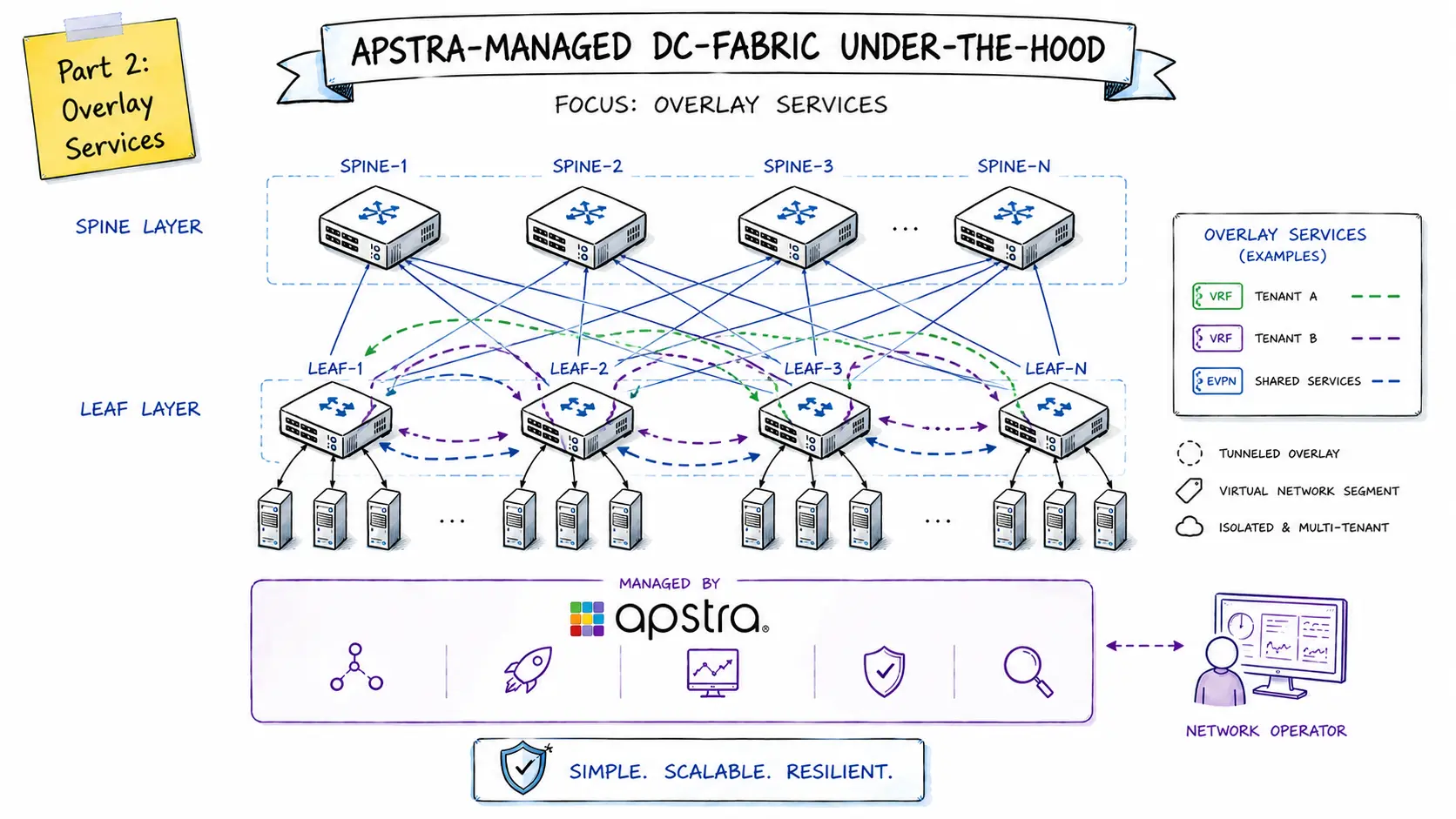
Part 2 - Overlay Services
This post is the second part of the series “Apstra Under the Hood”, which aims to provide a better understanding of Apstra as a solution and the DC fabrics it manages from a network engineer’s perspective.
While in the first part of this series I discussed the underlay network as a stable and high-performance foundation, in this post I’d like to focus on the design and implementation of the overlay services.
Target Design
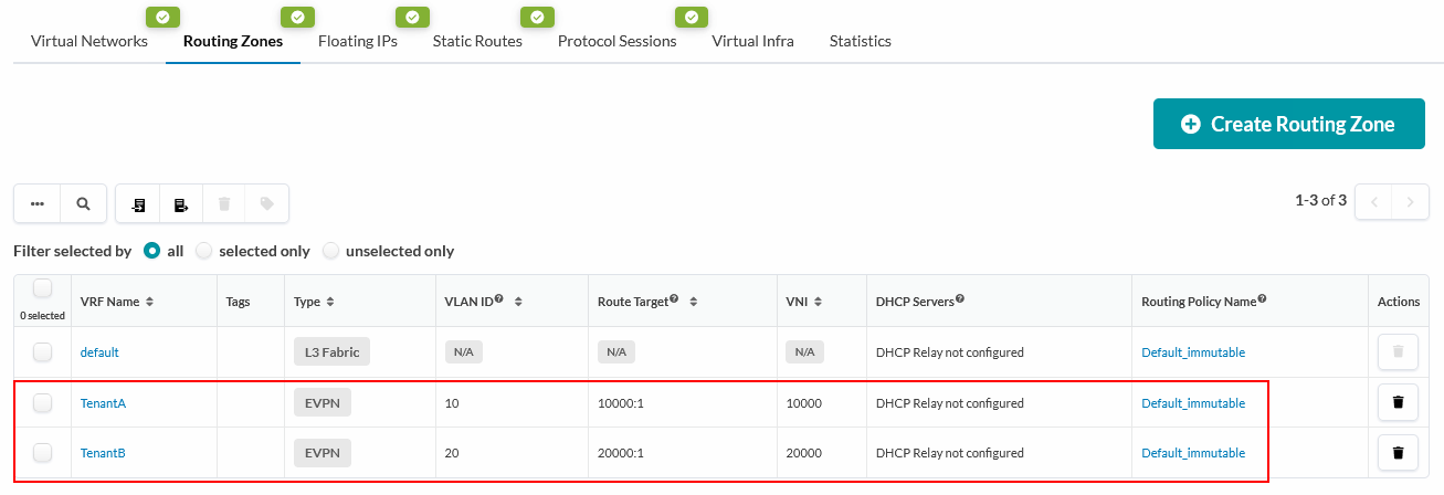
To illustrate how overlays work while taking into account as many different aspects and use cases as possible, I will implement the following target design in Apstra based on two different tenants (routing zones) with different routing configurations:
- TenantA:
- Asymmetric IRB
- VNI 10000
- TenantB
- Symmetric IRB
- VNI 20000
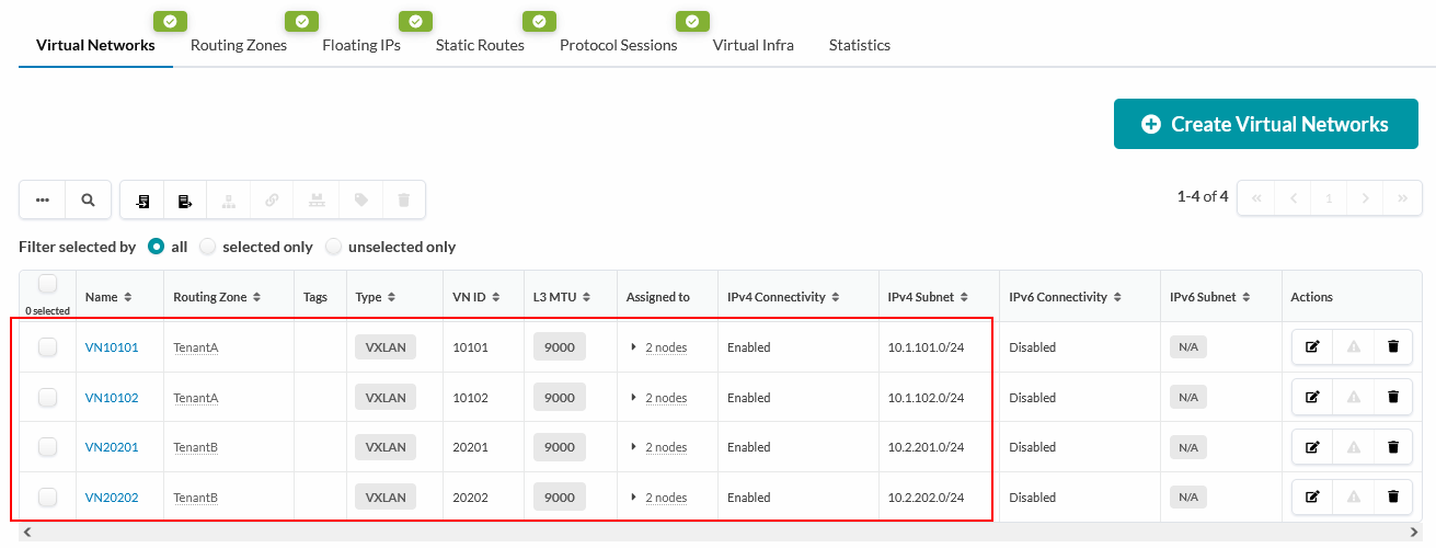
In total, I create two Layer 3 virtual networks per tenant, each including an anycast gateway, so that I can later illustrate the differences in inter-VNI routing:
| Routing Zone | VN Name | VNI | VLAN-ID | IP Addressing | Anycast-GW |
|---|---|---|---|---|---|
| TenantA | VN10101 | 10101 | 101 | 10.1.101.0/24 | 10.1.101.1 |
| VN10102 | 10102 | 102 | 10.1.102.0/24 | 10.1.102.1 | |
| TenantB | VN20201 | 20201 | 201 | 10.1.201.0/24 | 10.1.201.1 |
| VN20202 | 20202 | 202 | 10.1.202.0/24 | 10.1.202.1 |
Blueprint adjustments
The Demo Topology from the first part remains unchanged from a physical perspective. However, the following adjustments were made in the Virtual tab of the blueprint:
Routing Zones
 Virtual Networks
In addition, a Connectivity Template was created, which defines all of the above-mentioned virtual networks as tagged virtual networks. This Connectivity Template was assigned uniformly to all host ports, allowing the specific VNs/VLANs to be accessed flexibly on the host side.
EVPN-eBGP as control plane
When implementing the EVPN control plane, Apstra also relies on external BGP (eBGP), similarly to the underlay routing - leveraging the same ASN and router IDs. However, unlike underlay routing, in overlay routing, the eBGP peering connections are established between the lo0.0 loopback IP addresses of the spine and leaf switches. The necessary reachability is ensured by the underlay routing.
All BGP configurations relevant to the overlay or control plane can be found under the group l3clos-l-evpn (for all leaf switches) or l3clos-s-evpn (for all spine switches).
Using Leaf1 as an example, you can see that, similar to underlay routing, BGP multipath and multiple-as are also enabled at the group level for optimal load balancing across all available paths.
protocols {
    [...]
    bgp {
        [...]
        group l3clos-l-evpn {
            type external;
            multihop {
                ttl 1;
                no-nexthop-change;
            }
            family evpn {
                signaling {
                    loops 2;
                }
            }
            multipath {
                multiple-as;
            }
            bfd-liveness-detection {
                minimum-interval 3000;
                multiplier 3;
            }
            neighbor 203.0.113.0 {
                description facing_spine1-evpn-overlay;
                local-address 203.0.113.2;
                family evpn {
                    signaling;
                }
                export ( LEAF_TO_SPINE_EVPN_OUT && EVPN_EXPORT );
                peer-as 64512;
            }
            neighbor 203.0.113.1 {
                description facing_spine2-evpn-overlay;
                local-address 203.0.113.2;
                family evpn {
                    signaling;
                }
                export ( LEAF_TO_SPINE_EVPN_OUT && EVPN_EXPORT );
                peer-as 64513;
            }
            vpn-apply-export;
        }
        log-updown;
        graceful-restart {
            dont-help-shared-fate-bfd-down;
        }
        multipath;
    }
multihop is implemented with two more configuration options.- The
ttl 1option sets the Time-to-Live field in the IP header to 1 (the default value in Junos for multihop eBGP sessions is 64). This can be viewed, in a sense, as a security or efficiency measure, since the spine/leaf design ensures that the respective BGP peer is always only one hop away. This ensures that the BGP session is always established only via the direct spine uplinks. - The
no-nexthop-changeoption, on the other hand, is essential for the functionality of the EVPN control plane, particularly on the spine switches. Normally, when routes are advertised using eBGP, the BGP next-hop is repeatedly adjusted by the respective advertiser. EVPN routes, in particular, must always use the IP address of the originating VTEP as the next hop so that remote VTEPs can store the correct tunnel endpoints for specific destinations (e.g., MAC/IP addresses) in their forwarding logic. Theno-nexthop-changecommand ensures that the next-hop in EVPN routes is not changed during propagation.
At the group level, the EVPN address family is also configured using the statement family evpn signaling with the addition of loops 2.
In general, the loop prevention mechanism in eBGP is based on always checking the AS path of received routes to see if it contains the local ASN. If this is not the case, the route is accepted and propagated further; however, if the local ASN is part of the AS path, this is interpreted as a routing loop and the route is discarded.
The loops 2 option, however, means that the AS path is still interpreted as valid if it contains the local ASN up to two times for received routes.
In addition, for the EVPN peering connections, BFD with a detection time of 3x3000 ms is enabled, which is generally necessary to terminate the multihop eBGP sessions between the loopback IPs of spine and leaf switches within a reasonable amount of time (instead of waiting for the standard BGP hold timer of 90 seconds to expire), provided that connectivity is no longer available.
Policies
Leaf switches
Similar to the implementation of underlay routing, and as shown in the configuration excerpt above, the following two export policies are also enabled for the overlay eBGP sessions on all leaf switches:
LEAF_TO_SPINE_EVPN_OUTEVPN_EXPORT
Because the policies in the BGP configuration are logically combined with AND (export ( LEAF_TO_SPINE_EVPN_OUT && EVPN_EXPORT )), only routes that match both policies are propagated—even if the EVPN_EXPORT policy contains only a simple accept.
In detail, the relevant policies are as follows:
policy-options {
    [...]
    policy-statement EVPN_EXPORT {
        term EVPN_EXPORT-4095 {
            then accept;
        }
    }
    policy-statement LEAF_TO_SPINE_EVPN_OUT {
        term LEAF_TO_SPINE_EVPN_OUT-10 {
            from {
                protocol bgp;
                community FROM_SPINE_EVPN_TIER;
            }
            then reject;
        }
        term LEAF_TO_SPINE_EVPN_OUT-20 {
            then accept;
        }
    }
    [...]
    community FROM_SPINE_EVPN_TIER members 0:14;
}
The policy logic here is the same as in the underlay, because the EVPN export policies also ensure that a leaf switch propagates only its own EVPN routes (loopbacks / P2P links) to the spines. At the same time, this prevents routes learned from one spine to another spine—which are marked with the community FROM_SPINE_EVPN_TIER and the value 0:14—from being propagated further.
Spine switches
The policy implementation differs for spine switches. Here, only one export policy is defined for all leaf peers under the l3clos-s-evpn group - SPINE_TO_LEAF_EVPN_OUT. It is structured as follows:
policy-options {
    [...]
    policy-statement SPINE_TO_LEAF_EVPN_OUT {
        term SPINE_TO_LEAF_EVPN_OUT-10 {
            then {
                community add FROM_SPINE_EVPN_TIER;
                accept;
            }
        }
    }
    [...]
    community FROM_SPINE_EVPN_TIER members 0:14;
    [...]
}
The spine policies ensure that the spine forwards all EVPN routes received from the individual leaf switches to other leafs, but marks them with the community FROM_SPINE_EVPN_TIER with the value 0:14, so that leafs do not propagate these routes back to the spines.
Modular Overlay Implementation
In addition to the EVPN-side BGP configuration described above, the rest of Apstra’s overlay implementation consists of the following components, which are deployed exclusively on the leaf switches:
- MAC-VRF “evpn-1”
- L3 VRFs
- “TenantA”
- “TenantB”
- Host connectivity (individual port configurations)


MAC-VRF “evpn-1”
The mac-vrf routing instance named evpn-1 represents the fabric-wide L2 overlay domain and consolidates all relevant EVPN configurations. In addition to the global EVPN parameters, this part also includes all VLAN and VNI definitions, as shown here in the example of Leaf1:
routing-instances {
    [...]
    evpn-1 {
        instance-type mac-vrf;
        protocols {
            evpn {
                encapsulation vxlan;
                default-gateway do-not-advertise;
                duplicate-mac-detection {
                    auto-recovery-time 9;
                }
                extended-vni-list all;
                vni-options {
                    vni 10101 {
                        vrf-target target:10101:1;
                    }
                    vni 10102 {
                        vrf-target target:10102:1;
                    }
                    vni 20201 {
                        vrf-target target:20201:1;
                    }
                    vni 20202 {
                        vrf-target target:20202:1;
                    }
                }
            }
        }
        vtep-source-interface lo0.0;
        service-type vlan-aware;
        interface ae1.0;
        route-distinguisher 203.0.113.2:65534;
        vrf-target target:100:100;
        vlans {
            vn101 {
                description "VN10101---TenantA VN10101";
                vlan-id 101;
                l3-interface irb.101;
                vxlan {
                    vni 10101;
                }
            }
            vn102 {
                description "VN10102---TenantA VN10102";
                vlan-id 102;
                l3-interface irb.102;
                vxlan {
                    vni 10102;
                }
            }
            vn201 {
                description "VN20201---TenantB VN20201";
                vlan-id 201;
                l3-interface irb.201;
                vxlan {
                    vni 20201;
                }
            }
            vn202 {
                description "VN20202---TenantB VN20202";
                vlan-id 202;
                l3-interface irb.202;
                vxlan {
                    vni 20202;
                }
            }
        }
    }
[...]
}
The use and configuration of the MAC-VRF instance are, in principle, specified by the Apstra reference design. This also predefines that exactly one shared MAC-VRF instance is used for all tenants (or routing zones).
It is therefore not possible to use a separate MAC-VRF for each tenant, for example, to encapsulate all of a tenant’s EVPN routes in a tenant-specific MAC-VRF. To ensure that each individual VN/VLAN continues to function as an independent bridge domain under these conditions, the MAC-VRF service type vlan-aware was selected. (See also the overview of various MAC-VRF service types)
Global EVPN parameters include, among others, the following settings:
- Definition of the VTEP source interface (
lo0.0) - Definition of a leaf-specific route distinguisher (format:
<lo0.0-ip>:65534) - Definition of a uniform, domain-wide VRF route target (
target:100:100) - Definition of VXLAN data-plane encapsulation (
encapsulation vxlan) - Preventing the propagation of anycast gateway MAC addresses via EVPN (
default-gateway do-not-advertise) - Enabling duplicate MAC detection auto-recovery after 9 minutes (
duplicate-mac-detection auto-recovery-time 9)
For each Virtual Network or VNI, a separate VRF route target in the format target:<vni>:1 is also created to correctly export or import the corresponding VN-specific Type-2 or Type-3 EVPN routes to or from the associated VNs.
For each VLAN, the associated fabric-wide VNI is linked in addition to the switch-local VLAN ID. Additionally, the corresponding IRB interface is assigned for inter-VLAN/VNI routing in the overlay.
All active L2 switch ports defined in Apstra for connecting hosts (generic devices) are explicitly assigned to the MAC-VRF instance (e.g., ae1.0 in the example above).
L3 Tenant-VRFs
For each tenant or routing zone, a separate routing instance of type vrf is created, each of which bundles all overlay-specific Layer-3 configurations. On the one hand, these VRFs ensure the logical separation of individual tenants at the L3 level. On the other hand, they enable fabric-wide inter-VLAN/VNI routing within a tenant.
By default, Apstra creates a separate loopback interface per tenant on each leaf:
- TenantA:
lo0.2 - TenantB:
lo0.3
As I understand it, these loopback IPs do not initially serve any specific function, but should rather be viewed as a best practice — for example, to verify end-to-end reachability between specific leaf switches within tenants (possibly also using appropriate Apstra probes). Furthermore, they can be viewed as preparation for the future use of external L3 connections based on BGP, for example.
The tenant-specific loopback interfaces are also not used as route distinguishers, because Apstra uses a combination of the Lo0.0 IP address and the tenant-specific VLAN ID to define the VRF-specific route distinguisher: <lo0.0>:<vlan-id> (Example: Leaf1 - TenantA: 203.0.113.4:10)
The routing instance configurations generated by Apstra for TenantA and TenantB are largely similar, but differ in one aspect — depending on the routing configuration used (Asymmetric / Symmetric IRB), as shown here using Leaf1 as an example:
routing-instances {
    TenantA {
        instance-type vrf;
        routing-options {
            graceful-restart;
            multipath;
            auto-export;
        }
        protocols {
            evpn {
                ip-prefix-routes {
                    advertise direct-nexthop;
                    encapsulation vxlan;
                    vni 10000;
                    export BGP-AOS-Policy-TenantA;
                }
            }
        }
        description "TenantA VRF with asymmetric routing RT10000:1 VLAN10";
        interface irb.101;
        interface irb.102;
        interface lo0.2;
        route-distinguisher 203.0.113.4:10;
        vrf-target target:10000:1;
    }
    TenantB {
        instance-type vrf;
        routing-options {
            graceful-restart;
            multipath;
            auto-export;
        }
        protocols {
            evpn {
                irb-symmetric-routing {
                    vni 20000;
                }
                ip-prefix-routes {
                    advertise direct-nexthop;
                    encapsulation vxlan;
                    vni 20000;
                    export BGP-AOS-Policy-TenantB;
                }
            }
        }
        description "TenantB VRF with symmetric routing RT20000:1 VLAN20";
        interface irb.201;
        interface irb.202;
        interface lo0.3;
        route-distinguisher 203.0.113.4:20;
        vrf-target target:20000:1;
    }
    [...]
}
In TenantB, Symmetric IRB is enabled using the L3-VNI 20000 (irb-symmetric-routing vni 20000), so that inter-VNI routing always takes place via this L3-VNI.
In TenantA, which uses asymmetric routing, inter-VNI routing, on the other hand, always takes place at the ingress VTEP into the destination VN, so that packets are then forwarded VN-locally to the egress VTEP.
target:<l3-vni>:1.For both tenants, the L3-VNI is also configured for EVPN Type-5 routes (ip-prefix-routes vni <l3-vni>). In addition, Apstra uses the advertise direct-nexthop option for these Type-5 routes. This ensures that the Router MAC Extended Community is appended to the corresponding IP prefix routes to signal the destination MAC address of the internal Ethernet header to remote VTEPs.
Furthermore, individual EVPN IP prefix route export policies are defined in the corresponding VRF configurations for the L3 routing instances of each tenant:
BGP-AOS-Policy-TenantABGP-AOS-Policy-TenantB
In detail, the relevant policies are as follows:
policy-options {
    [...]
    policy-statement AllPodNetworks-TenantA {
        term AllPodNetworks-TenantA-10 {
            from {
                family inet;
                protocol direct;
            }
            then {
                community add TENANTA_COMMUNITY_V4;
                accept;
            }
        }
        term AllPodNetworks-TenantA-100 {
            then reject;
        }
    }
    policy-statement AllPodNetworks-TenantB {
        term AllPodNetworks-TenantB-10 {
            from {
                family inet;
                protocol direct;
            }
            then {
                community add TENANTB_COMMUNITY_V4;
                accept;
            }
        }
        term AllPodNetworks-TenantB-100 {
            then reject;
        }
    }
    [...]
    policy-statement BGP-AOS-Policy-TenantA {
        term BGP-AOS-Policy-TenantA-10 {
            from policy AllPodNetworks-TenantA;
            then accept;
        }
        term BGP-AOS-Policy-TenantA-100 {
            then reject;
        }
    }
    policy-statement BGP-AOS-Policy-TenantB {
        term BGP-AOS-Policy-TenantB-10 {
            from policy AllPodNetworks-TenantB;
            then accept;
        }
        term BGP-AOS-Policy-TenantB-100 {
            then reject;
        }
    }
    [...]
    community TENANTA_COMMUNITY_V4 members [ 3:20007 21002:26000 ];
    community TENANTB_COMMUNITY_V4 members [ 3:20007 21003:26000 ];
}
These policies ensure that all directly connected IPv4 networks (e.g., tenant-specific loopback IPs of the leaf switches and the subnets of the IRB interfaces) of both VRFs are also propagated as EVPN Type-5 routes via eBGP within the fabric. The EVPN routes are marked with the following communities:
- TenantA:
TENANTA_COMMUNITY_V4with the values3:20007and21002:26000 - TenantB:
TENANTV_COMMUNITY_V4with the values3:20007and21003:26000
Although the communities mentioned above are not actively referenced as filter criteria in any relevant routing policies, I suspect that Apstra uses these communities as part of anomaly detection and telemetry analysis to verify the end-to-end functionality of the fabric.
Host connectivity
Individual host connectivity is a combination of the following two aspects, which are managed in different places within Apstra:
- physical connection - defined by the mapping of Generic Devices and their connection to the leaf switches
- logical connection - defined by the Connectivity Templates assigned to the individual host-facing switch ports of the leaf switches
When implementing host connectivity using Apstra, there are essentially two connection variants that result in different configurations:
- standalone ports (e.g., “Host2” and “Host3”)
- ESI multihoming (e.g., “Host1”)
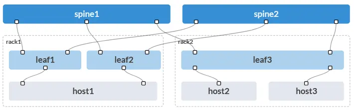
ge-0/0/2 and ge-0/0/3:interfaces {
[...]
ge-0/0/2 {
description to.host2;
mtu 9192;
unit 0 {
family ethernet-switching {
interface-mode trunk;
vlan {
members [ vn101 vn102 vn201 vn202 ];
}
}
}
}
ge-0/0/3 {
description to.host3;
mtu 9192;
unit 0 {
family ethernet-switching {
interface-mode trunk;
vlan {
members [ vn101 vn102 vn201 vn202 ];
}
}
}
}
[...]
}
For redundantly connected hosts, in combination with ESI multihoming, things get a bit more complex, as can be seen here in the example of the Leaf1 port ge-0/0/2, which is assigned to the LAG interface ae1.0:
interfaces {
    [...]
    ge-0/0/2 {
        description to.host1;
        ether-options {
            802.3ad ae1;
        }
    }
    [...]
    ae1 {
        description to.host1;
        mtu 9192;
        esi {
            00:02:00:00:00:00:01:00:00:01;
            all-active;
        }
        aggregated-ether-options {
            lacp {
                active;
                system-id 02:00:00:00:00:01;
            }
        }
        unit 0 {
            family ethernet-switching {
                interface-mode trunk;
                vlan {
                    members [ vn101 vn102 vn201 vn202 ];
                }
            }
        }
    }
    [...]
}
On the LAG interface ae1.0, Apstra also implements the following settings:
- Ethernet Segment Identifier (ESI) - e.g.,
esi 00:02:00:00:00:00:01:00:00:01: The ESI value, which must be identical on both connecting leaves (Leaf1 and Leaf2 in this case) and which is used in the various EVPN route types for multihomed hosts, is automatically set by Apstra. This value must be unique across the fabric, which Apstra ensures through a blueprint-internal counter. The suffixall-activeindicates that all active host ports are used for forwarding. (This is the default configuration in Apstra and cannot be customized.)TipTo ensure that ESI IDs remain unique across blueprints and pods in the context of a DCI-based interconnection, the so-called most-significant-byte ("msb") — or the second octet of the ESI — can be adjusted in the blueprint settings (default value 02). In Apstra 6.1.2, this parameter can be found under “Staged” > “DCI” > “Settings.” By default, the first octet of the ESI must always be 00 -> e.g., 00:02:[…] - LACP System ID (if enabled) — e.g.,
lacp system-id 02:00:00:00:00:01: The LACP System ID, which must be identical on both connecting leaves and which is signaled to the multi-homed hosts, is automatically and uniformly assigned by Apstra in the same way as the ESI.
Conclusion
Compared to the last article on the underlay network, this post has become much more comprehensive. Despite the complexity, I’ve tried to explain all relevant aspects of the overlay implementation — from the BGP setup to the various routing instances and port configurations — as clearly as possible while still keeping it concise.
I hope that this second part of the “Apstra Under the Hood” series will also help you better understand the design and implementation of overlay services — as well as the building blocks used for them in Apstra-managed DC fabrics with Juniper fabric switches. In my view, this clearly demonstrates once again the overall complexity that Apstra manages down to the very granular implementation level. Ultimately, all configurations on all participating fabric switches must work together seamlessly to ensure end-to-end functionality.
Given the length of this article, I will not include a separate section on the verification of overlay services at this point. I will address this aspect in the next part of the series and explain in detail how the implementations described here can be verified using appropriate show commands.